how does induction cooker heating work
Electromagnetic induction is widely used in cooking all over the world Cooking.Between now and 2018, the induction cooker market will Grew at a compound annual growth rate of 6.83% (according to industry TechNavio).However, induction cooking Kewlinary ways are unique to each region Development path is very different.This article will take a look at the accuracy resonant cookers have different equivalent circuits and involve different use the coil properties of the pan material.

Figure 1: Quasi resonant circuit
There are several induction cooker circuit topologies, each one for a particular region of the world.In Europe, more Unit, half - bridge resonant stoves are becoming more and more common. But in Asia it is different.For example, millions per year Single-unit, quasi-resonant stoves were sold to China Consumer, while using a quasi resonant inductor topology Korean rice cookers have seen a sizable market in South Korea Appeal.
For a single unit cooker or rice cooker circuit, a quasi resonant booster circuit is usually used (as shown in Figure 1).This type of circuit has fewer components the number.They typically rely on a 1200V or 1350V IGBT and can be connected to a rectified and filtered 120V or 240V AC line.The R L C resonant circuit is connected to the rectifier AC input through the IGBT switch. In preferred operation mode, the IGBT conducts and stores energy in the inductor and capacitor.When it is off, the circuit resonates and the voltage rises sinusoidal above the input level.When the voltage loop is grounded, the switch re-conducts and stores energy again.Although the inductor and capacitor parts of the R L C structure are obvious in this schematic diagram, the resistance is not.The pot acts as a magnetic core and an inductor resistance, thereby producing a load (or damping) resistance.Without the pot, the voltage would rise very high because it is a very highly charged circuit.This may damage the IGBT.The induction cooker will incorporate a protective circuit to protect it from the "no pot" situation.
The equivalent circuit with a pot is detailed in Figure 2.If we consider the resistance of the pot as the core loss of the circuit, it will be in parallel with the two L C elements.But some of the data suggests connecting it in series with the inductor.This conversion can be used for AC analysis, but is not suitable for DC equivalent circuits because inductance impedance is usually measured in m ohms, and adding 20 to 100 ohms in series will obviously change it.However, many simulations employ such series equivalencies (which are given in the figure shown later).
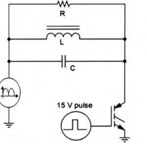
Figure 2:Quasi resonant RLC circuit
The damping resistance R seen in the equivalent circuit is composed of two different loss mechanisms.This first loss mechanism is due to eddy currents, which are inherent in any conductive material.In addition, if a magnetic material is used in a pan, hysteresis losses are considered.Most current induction cookers are completely magnetic.The development of a circuit suitable for non-magnetic pans is under way.
Eddy current and its role in induction cooker
Eddies are annular currents in the conductance caused by the application of different magnetic fields.The principle behind it is derived from the law of electromagnetic induction, formulated by Faraday nearly 200 years ago, which states that any change in the density of the magnetic field in a conducting coil will create a voltage within the coil. Changes in the magnetic field near the pot will generate a small voltage inside, and due to the pot's low impedance, current will flow through the metal.This is then converted to heat energy, heating the food in the pan.Eddy currents occur in any conductor, regardless of its magnetism.The vortex is concentrated near the conductive surface and decreases exponentially with the distance from the surface.

Where, δ is skin depth (measured by "), μ(permeability)=1.257× 10⁻⁶h /m, and σ is conductivity
Most pot designs show that they are significantly thicker than skin depth.The two most widely used stainless steel alloys for induction cookers are 430 and 304.
For alloy 430, the resistivity (R h O) is 2.6× 10⁶ (1/ ω m).This means that the skin depth is:

For alloy 304, the r h O value is 1.45× 10⁶ (1/ ω m).So the resulting skin depth is:

The role of hysteresis loss in induction cooker
Hysteresis losses occur in all materials whose permeability is greater than that of air.Most induction cookers require a magnetic cooker because the increased loss improves the overall performance of the induction cooker.When the magnetic field applied to a magnetic material increases and then drops to its initial value, the resulting field within the material cannot return to its initial level in a corresponding manner.The difference is hysteresis loss.The hysteresis loss, which results from heat generated by the rearrangement of the magnetic field, is proportional to the frequency of the magnetic field and is the flux density to the NTH power.The relationship is described by the following equation:
![]()
Where: B H is the hysteresis loss (W/u n I t mass), f is the flux frequency (Hz), Bmax is the maximum value (Gauss), Kh is the hysteresis constant (which varies with the cooker material), n is the Steinmetz index (which also varies with the cooker material).

Figure 3:Material waveform of different POTS (dc power input)

Figure 4:The relationship between the inductance and frequency of magnetic and non-magnetic pans
The coil features
Induction cooker usually uses quasi - resonant power section or half - bridge resonant circuit.The coil characteristics are the same regardless of the circuit.High-frequency, high-current pulses are applied to the coil, creating a high magnetic field that is then absorbed by the pot and converted into heat.As explained, the pot acts as a damping resistance for the L and C circuits.Although it is possible to measure inductance and capacitance values, the final circuit is much more complex.As the core of the inductor coil, the pot changes its parameters.
The test data collected in FIG. 3 show the effect of various kettle materials used for the quasi-resonant circuit on the standard 110μH coil.The material properties of the pot placed on the surface of the cooker greatly affect the measured inductance and resistance.The resistance in these measurements is used as a series resistance and can be effectively used in the AC model.The waveform shows the damping of the different pot materials
Effect.The difference in damping between non-magnetic, magnetic (cast iron and stainless steel) and non-magnetic (aluminum) pans can be clearly seen in a separate screen shot.Figure 4 is derived from this, showing the frequency dependent inductance changes and losses for each of the same POTS.

Figure 5: The relationship between series resistance and frequency of magnetic and non-magnetic pans
As we have seen, there are two main effects that cause heat to be generated in the induction vessel.Non - magnetic pans can generate heat entirely from eddy current losses.The magnetic pot uses eddy current loss and hysteresis loss.As a result, they provide greater energy efficiency for induction cooking applications.In Figure 5, the curves of the magnetic pans are very close to each other and clearly distinguishable from those of non-magnetic materials.In addition, the impedance of the coil (actual and induced) varies greatly with the material of the pot and the driving frequency of the power supply circuit.
No Comments